
DKM1150SV Unloading and Installation Process
1. make machine Foundation load (following picture1)

. According to following drawing, make the square hole on the ground where the customer want to install the machine, (hole size 200mm* 200mm square , depth 1000mm)
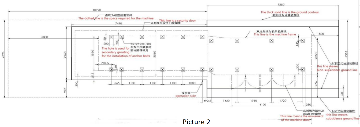
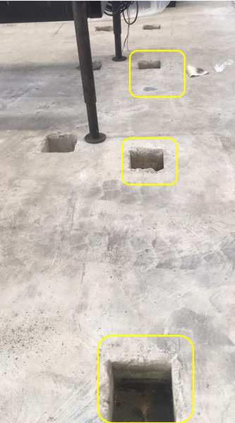
Following is the picture for your reference.
2. Put following Anchor in each hole(do not add cement in this step)
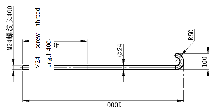
Picture 3
3. Prepare the machine feet (20 pieces), put them behind these square hole
DKM – 1150SV Unloading Process
DKM-1150SV Preparation for Unloading Process
1. One set forklift that can bear 10-15T
2. One set crane that can bear 50T weight, or travelling crane that can bear 35- 50T.
3. Two 10-20m ropes that can bear 20T or more weight; Two 10-20m wireropes with diameterφ16.
4. Two jacks that can bear 5-10T weight.
5. Unloading in factory by using crane, this required plant door height 8m or more, door width 6m or more, plant floor height 15m height or more.
Unloading in factory by using driving, this required plant door 8m height or more, door width 6m or more, plant floor height 10m height or more.
For DKM – 1150SV Clamping Frame
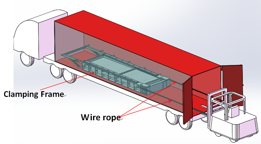
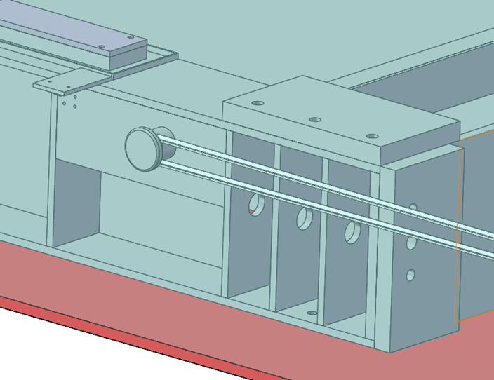
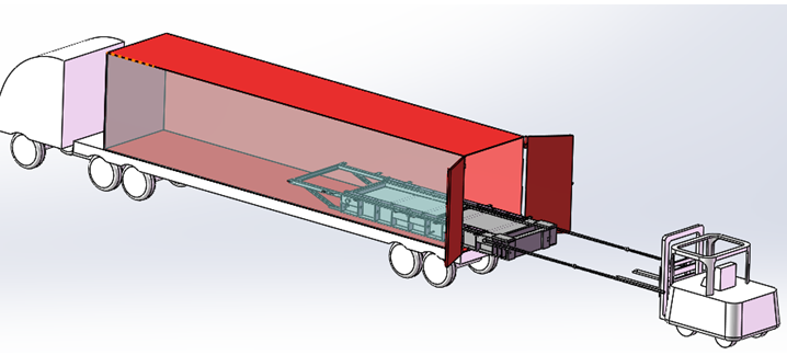
When the forklift pull frame out of the container 500mm, it needs remove the rope, and then carefully and slowly move out the frame by forklift,
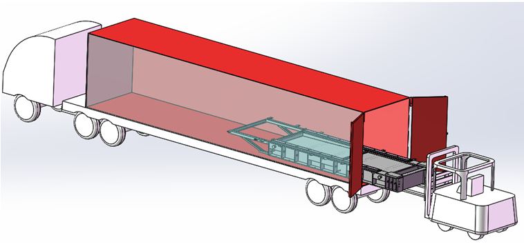
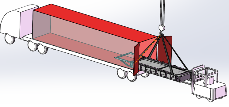
When it’s ok to use crane to sling the frame, do it and lift the frame out of the container,
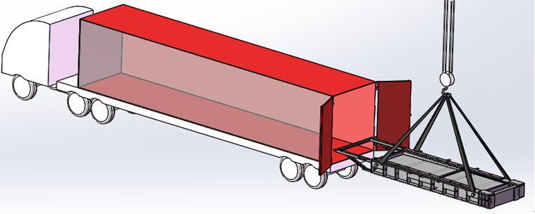
Finally put it to the place where it shall be.
DKM-1150SV Installation Process
Preparation before installation
1. Prepare one pc 5-10T sling, one 5-10T Jack, 1.5m and 0.5m level or a level of each one, the foundation bearing chart
The bearing requirements of the machine to the foundation are as follows
2. Customer needs to provide the factory floor plan and customer's water, electricity, gas preparation, in order to engineer installation and display
DKM-1150T Installation
1. Install the frame, and level it (by adjusting the shocks proof foot)
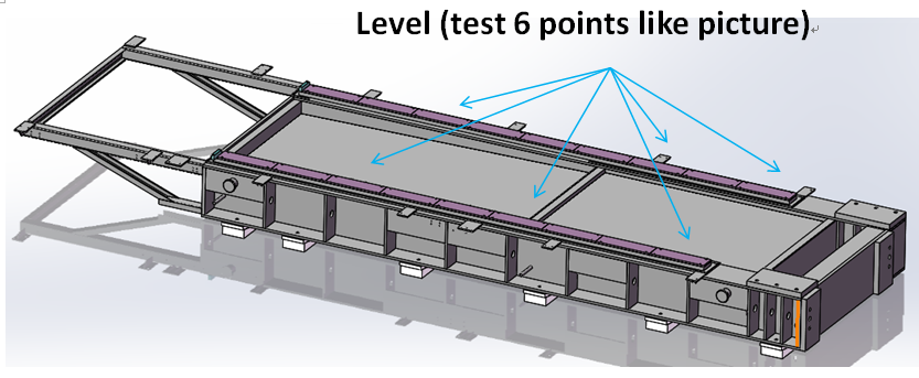
2. After machine base is put on feet, measuring the frame level, measures three points in balance ( by adjusting feet), and the tolerance value is ±0.1mm, auxiliary measuring board should be parallel, with tolerance ±0.02mm
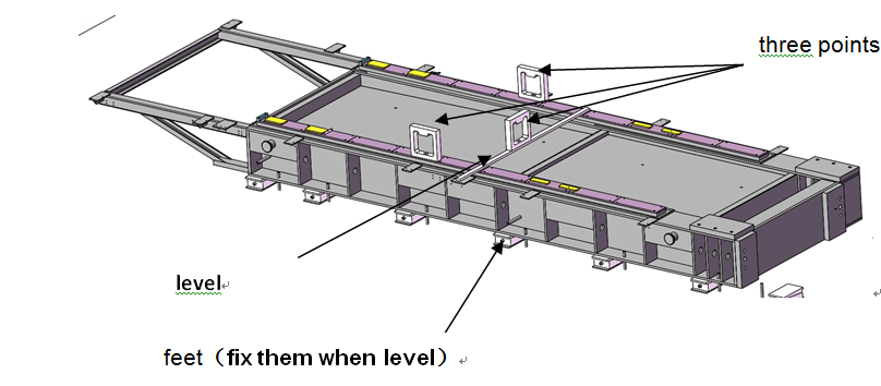
3. After machine base is in balance, then add cement in these square hole. Waiting for dry.
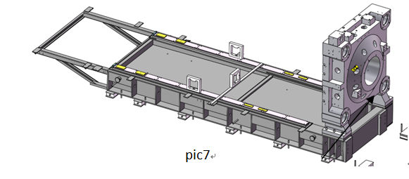
4. Install the front plate (pic 7)
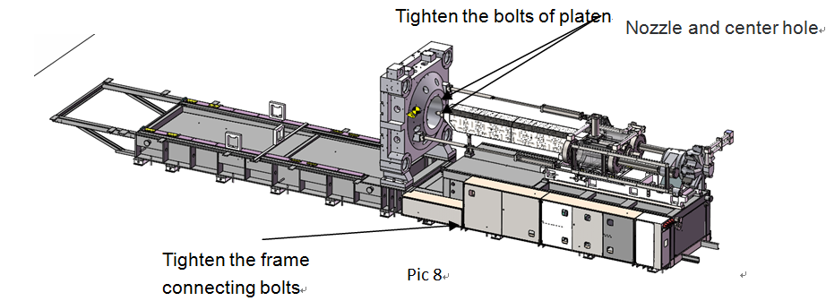
Install injection unit and machine frame (Figure 8), pls pay attention, the center of the front plate and the machine nozzle should in the same center, the Concentricity tolerance±0.5mm ±0.5mm.
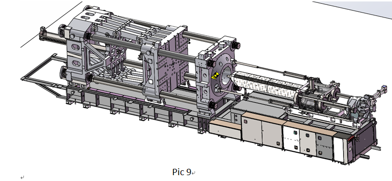
5. Install the clamping parts (pic 9)
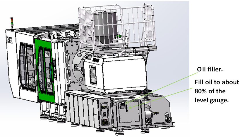
6. Connect all high pressure hose and plug, install all electronic rulers, hydraulic valve plug, connect power to electric box, add Hydraulic oil 46# to oil tank
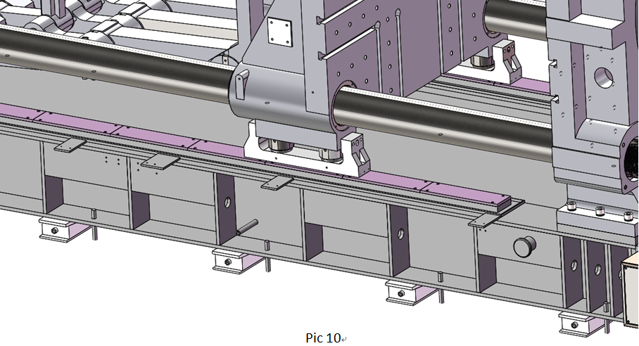
7. Loose floating cylinder fixing screws (pic 10)
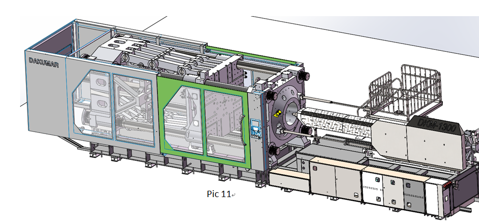
8. Install the machine stroke switch, then install the clamping bracket, install the machine door (picture 11)
DKM-1150SV Machine Level Alignment
1. level clamping frame
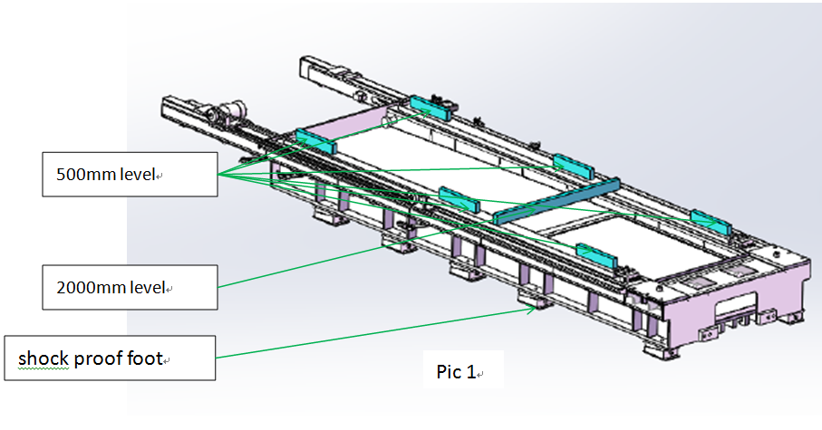
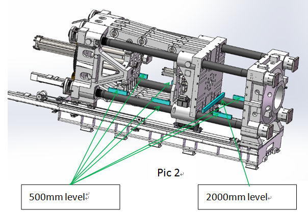
As pic 1, level the frame by levels and adjust the feet to make it level, the difference shall not be greater than 0.1mm/m.
2. As pic 2, install the clamping part, level the clamping part, it require the difference shall not be greater than 0.05mm/m.
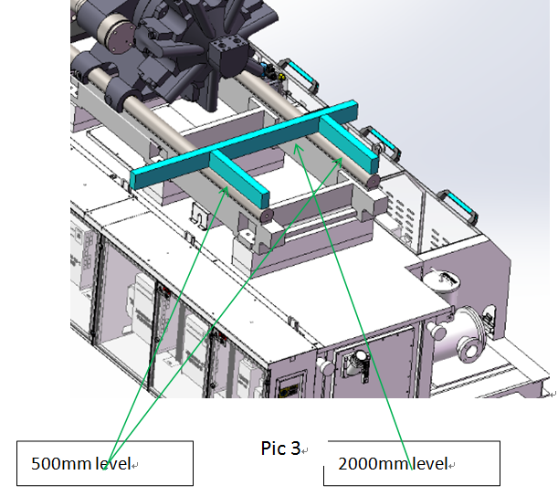
3. As pic 3, install the injection unit, level the injection part, it require the difference shall not be greater than 0.5mm/m.
DKM-1150SV Fill Hydraulic Oil & Connect Cooling Tubes for Machine
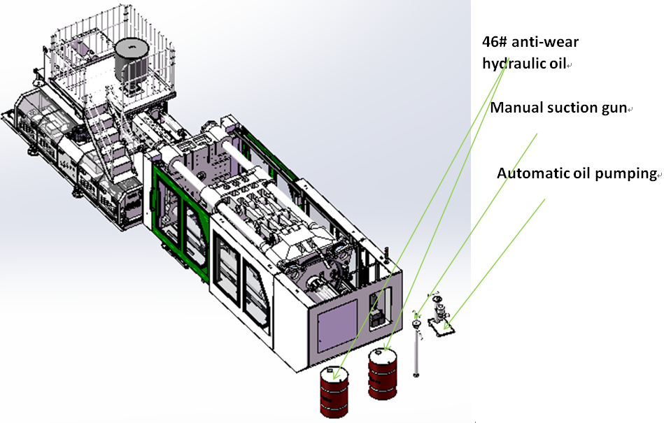
Fill hydraulic oil to the injection molding machine, 46# hydraulic oil for mean climatic temperature 0 ℃ to 40 ℃; 32# for about 0 ℃ to 10 ℃.
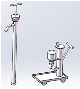
Auxiliary equipment needed for pumping unit (manual or semi-automatic)
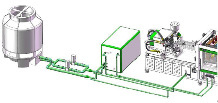
According to the water layout of workshop and local standard, connect the one inch of water pipe to machine cooling connector. Note, the principle for machine cooling connector is down in, up out or right in and left out.
DKM-1150SV Electrical Connection Process and Notes
1. Inspection the voltage and frequency fit the machine specified. Check the nameplate, such as: 220V, 380V, 415V, 440V etc.
2. Select the corresponding cable to prevent the short circuit accident caused by over current.
3. check the machine model、voltage、phase sequence,Prevent the wrong connection (cause equipment damage).
Machine power = voltage (V) * current (A), calculate the wire specifications, to match with the wire correctly.
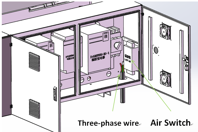
3.1. Connect the electricity according to the U/V/W. As the figure shows:
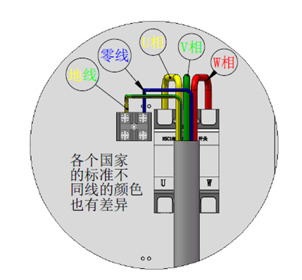
3.2. The zero line of distribution cabinet is connected to the N;
3.3. The ground wire of distribution cabinet is connected to the symbol of Ground Line.
4. Turn off electrical power and under the principle of up in down out, connect the power of the injection molding machine first, and then connect the distribution cabinet; to prevent the misoperation of others.
5. On equipment wiring,according to first connect the equipment on the line (switch off), then connect to the power distribution cabinet breaker (or air) principle; distribution cabinet wiring should first disconnect the circuit breaker, with a pencil or a multi-meter to test, to ensure that no voltage, lord it can be connected to power line equipment.
6. When supply the powers, turn on the distribution cabinet at first, and then turn on the equipment.
7. Turn off the power, turn off the equipment firstly, and then turn off the distribution cabinet.
8. When disconnecting wires, remove the power supply line of the distribution cabinet, and then remove the wires on the equipment.
9. During equipment repair, turn off the circuit breaker and sign the "do not turn on" on the main switch.
DKM-1150SV Auxiliary Equipment Installation and Connect Power and Notes:
Connect the auxiliary equipment to the injection molding machine or other machinery one by one.
1、 Dryer Installation (attached drawing)
2、 Auto Loader Installation (attached drawing)
3、 Chiller Installation (attached drawing)
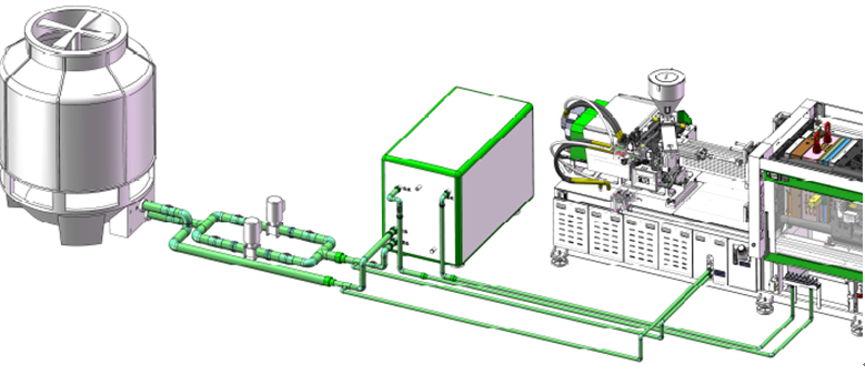
1. All high-power auxiliary machines shall be connected on power distribution box.
2. For those auxiliary machineries, connected to plastic injection machine, check the power and the corresponding size of the aviation socket switch.
3. After testing, turn off all the machineries, avoid accident because of the dry running.
4. When connect the electricity, pay attention to the safety of electricity, only connect allowed when confirm no electricity.
5. When connecting powers, connect with the auxiliary equipment firstly, and then connect the distribution cabinet;
When disconnecting, remove the line of the power distribution cabinet at first, and then dismantle the power line on the equipment.
